
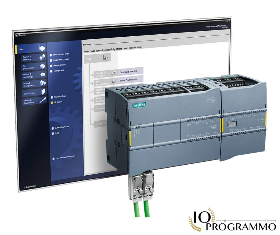
Are you ready to elevate your PLC programming skills? Dive into our technical tutorial on “Connecting Factory I/O to Siemens TIA Portal” and discover how to seamlessly integrate Siemens S7-PLCSIM with TIA Portal. Compatible with Windows 10/11, this guide supports Modbus, OPC UA, and Allen-Bradley. Start with creating a project in TIA Portal, configure PLCSIM, select the Siemens driver in Factory I/O, and map your I/O. Write ladder logic to transition from a simple lamp to a sensor-driven system, and then start your simulation. Learn to debug common errors like firewall issues, data type mismatches, and wrong addresses. With a 30-day free trial, you can practice hands-on without costly hardware, perfect for exam and job preparation. Ready to test your skills? Start your trial now.
In particolar modo vedremo:
Quick Solution: Solve the Problem Quickly
Prerequisites: Setting Up Your TIA Portal Environment
Before diving into the technical tutorial, ensure your TIA Portal environment is properly configured. Begin by installing the latest version of TIA Portal compatible with your operating system. Verify that your system meets the minimum requirements, including Windows 10/11 compatibility. Additionally, ensure you have the necessary licenses and drivers for Siemens S7-PLCSIM and Factory I/O installed.
To proceed, you will need:
- TIA Portal software
- Siemens S7-PLCSIM
- Factory I/O software
- A computer running Windows 10/11
Once installed, launch TIA Portal and create a new project. This will serve as the foundation for your simulation setup.
Procedure: Step-by-Step PLCSIM Configuration
Follow these steps to configure PLCSIM within TIA Portal:
- Open TIA Portal and create a new project. Name it appropriately for easy identification.
- Navigate to the ‘Hardware Catalog’ and select ‘Siemens S7-PLCSIM’. Add it to your project.
- Configure the PLCSIM with the correct addresses. Ensure that the addresses match those you plan to use in Factory I/O.
- In Factory I/O, select the Siemens driver. This will enable communication between Factory I/O and PLCSIM.
- Map the digital and analog I/O between Factory I/O and PLCSIM. This step is crucial for accurate simulation.
- Write the ladder logic in TIA Portal. For example, create a simple program where a lamp is controlled by a sensor input.
- Start the simulation in Factory I/O. Monitor the behavior of your program and make adjustments as necessary.
Verification: Debugging and Testing Your Simulation
After setting up your simulation, it’s essential to verify its functionality. Begin by running the simulation and observing the behavior of your program. If you encounter issues, follow these steps to debug common errors:
- Firewall Settings: Ensure that the firewall is not blocking communication between Factory I/O and PLCSIM.
- Data Type Mismatch: Verify that all data types are correctly configured and match between Factory I/O and PLCSIM.
- Wrong Addresses: Double-check that the addresses used in your program are accurate and correspond to the correct I/O points.
By following these steps, you can ensure that your simulation runs smoothly and accurately reflects your intended program logic.
Setting Up TIA Portal: Initial Project Configuration
Creating Your First TIA Project: Step-by-Step Guide
To begin your journey with TIA Portal, you need to create a new project. Launch TIA Portal and select ‘Create New Project’. Name your project clearly, such as ‘PLCSIMIntegrationProject’, to ensure easy identification. This project will be the foundation for your simulation setup. Ensure your TIA Portal version is compatible with your operating system, specifically Windows 10/11, to avoid any compatibility issues.
Once the project is created, you will be prompted to select the hardware configuration. Navigate to the ‘Hardware Catalog’ and choose ‘Siemens S7-PLCSIM’. This selection is crucial as it enables the integration of Factory I/O with TIA Portal, allowing for a realistic virtual plant simulation. Confirm your selection and proceed to the next step.
Configuring PLCSIM: Setting Correct Addresses for Simulation
After adding PLCSIM to your project, the next step is to configure it with the correct addresses. This is a critical step to ensure that your simulation accurately reflects the intended hardware setup. Open the PLCSIM configuration window and input the addresses that correspond to the I/O points you plan to use in Factory I/O. For example, if you are simulating a sensor input, ensure that the address in PLCSIM matches the address in Factory I/O. This alignment is necessary for the seamless communication between the two platforms.
It is advisable to refer to the TIA Portal documentation and Factory I/O user manual for specific address configurations. These resources provide detailed information on the correct address ranges and technical parameters, ensuring that your simulation setup adheres to industry standards such as IEC 61131-3 for programmable controllers.
Mapping Factory I/O: Connecting Digital and Analog Signals
With PLCSIM configured, the next step is to map the digital and analog I/O between Factory I/O and PLCSIM. This mapping is essential for accurate simulation and ensures that the signals are correctly interpreted by both platforms. In Factory I/O, select the Siemens driver to enable communication with PLCSIM. Then, navigate to the I/O mapping section and match the digital and analog signals between the two platforms.
For instance, if you are simulating a lamp controlled by a sensor input, map the sensor input address in Factory I/O to the corresponding address in PLCSIM. This step requires careful attention to detail to ensure that the signals are correctly routed and that the simulation behaves as expected. Refer to the Factory I/O documentation for detailed instructions on mapping I/O signals and troubleshooting common issues.
Configuring PLCSIM: Addressing for Virtual Plant
Configuring PLCSIM: Setting Up Standards for Virtual Plant
To ensure your virtual plant simulation is both accurate and compliant with industry standards, it is crucial to configure PLCSIM correctly. Begin by setting up the hardware configuration in TIA Portal. Navigate to the ‘Hardware Catalog’ and select ‘Siemens S7-PLCSIM’. This selection is pivotal as it allows TIA Portal to connect to a realistic virtual plant, facilitating hands-on practice without the need for costly hardware. Ensure your TIA Portal version is compatible with your operating system, specifically Windows 10/11, to avoid any compatibility issues.
Refer to the TIA Portal documentation for specific configuration guidelines. These resources provide detailed information on the correct address ranges and technical parameters, ensuring that your simulation setup adheres to industry standards such as IEC 61131-3 for programmable controllers. This alignment is necessary for the seamless communication between TIA Portal and Factory I/O.
Configuring PLCSIM: Defining Parameters for Accurate Simulation
After adding PLCSIM to your project, the next step is to define the parameters for accurate simulation. Open the PLCSIM configuration window and input the parameters that correspond to the I/O points you plan to use in Factory I/O. For example, if you are simulating a sensor input, ensure that the parameters in PLCSIM match the parameters in Factory I/O. This alignment is necessary for accurate simulation and ensures that the signals are correctly interpreted by both platforms.
It is advisable to refer to the TIA Portal documentation and Factory I/O user manual for specific parameter configurations. These resources provide detailed information on the correct parameter ranges and technical specifications, ensuring that your simulation setup adheres to industry standards such as IEC 61131-3 for programmable controllers. This alignment is necessary for accurate simulation and ensures that the signals are correctly interpreted by both platforms.
Configuring PLCSIM: Implementing Correct Addresses for I/O Mapping
With PLCSIM configured, the next step is to implement the correct addresses for I/O mapping. This mapping is essential for accurate simulation and ensures that the signals are correctly interpreted by both platforms. In Factory I/O, select the Siemens driver to enable communication with PLCSIM. Then, navigate to the I/O mapping section and match the digital and analog signals between the two platforms.
For instance, if you are simulating a lamp controlled by a sensor input, map the sensor input address in Factory I/O to the corresponding address in PLCSIM. This step requires careful attention to detail to ensure that the signals are correctly routed and that the simulation behaves as expected. Refer to the Factory I/O documentation for detailed instructions on mapping I/O signals and troubleshooting common issues.
Note: Ensure that the addresses used in your program are accurate and correspond to the correct I/O points. Double-check that the addresses in PLCSIM match those in Factory I/O to avoid any communication errors.
Integrating Siemens Driver in Factory I/O
Step-by-Step Guide to Siemens Driver Integration
To seamlessly integrate the Siemens driver in Factory I/O, you must follow a structured approach to ensure compatibility and accurate simulation. Begin by creating a new project in TIA Portal. This foundational step sets the stage for your virtual plant simulation, allowing you to configure the Siemens S7-PLCSIM with the correct addresses. Ensure your TIA Portal version is compatible with your operating system, specifically Windows 10/11, to avoid any compatibility issues.
Next, navigate to the ‘Hardware Catalog’ in TIA Portal and select ‘Siemens S7-PLCSIM’. This selection is crucial as it enables the integration of Factory I/O with TIA Portal, allowing for a realistic virtual plant simulation. Confirm your selection and proceed to configure the PLCSIM with the correct addresses. This step is essential for accurate simulation and ensures that the signals are correctly interpreted by both platforms. Refer to the TIA Portal documentation for specific configuration guidelines to adhere to industry standards such as IEC 61131-3 for programmable controllers.
Setting Up Siemens S7-PLCSIM in Factory I/O
With PLCSIM configured, the next step is to set up the Siemens S7-PLCSIM in Factory I/O. In Factory I/O, select the Siemens driver to enable communication with PLCSIM. This step is pivotal as it allows for the seamless integration of Factory I/O with TIA Portal, facilitating hands-on practice without the need for costly hardware. Ensure that the addresses in PLCSIM match those in Factory I/O to avoid any communication errors.
For instance, if you are simulating a lamp controlled by a sensor input, map the sensor input address in Factory I/O to the corresponding address in PLCSIM. This step requires careful attention to detail to ensure that the signals are correctly routed and that the simulation behaves as expected. Refer to the Factory I/O documentation for detailed instructions on mapping I/O signals and troubleshooting common issues.
Mapping and Debugging Siemens I/O Connections
After mapping the digital and analog I/O between Factory I/O and PLCSIM, the next step is to write the ladder logic in TIA Portal. For example, create a simple program where a lamp is controlled by a sensor input. This step is crucial for accurate simulation and ensures that the signals are correctly interpreted by both platforms. Start the simulation in Factory I/O and monitor the behavior of your program.
If you encounter issues, follow these steps to debug common errors: ensure that the firewall is not blocking communication between Factory I/O and PLCSIM, verify that all data types are correctly configured and match between Factory I/O and PLCSIM, and double-check that the addresses used in your program are accurate and correspond to the correct I/O points. By following these steps, you can ensure that your simulation runs smoothly and accurately reflects your intended program logic.
Note: Ensure that the addresses used in your program are accurate and correspond to the correct I/O points. Double-check that the addresses in PLCSIM match those in Factory I/O to avoid any communication errors.
Mapping Digital/Analog I/O: A Step-by-Step Guide
Step 1: Setting Up Your TIA Portal Project
To begin your journey with Factory I/O integration, start by creating a new project in TIA Portal. This foundational step is crucial for setting up a realistic virtual plant simulation. Ensure you are using a compatible version of TIA Portal, specifically designed for Windows 10/11. This compatibility ensures a seamless experience and adherence to industry standards such as IEC 61131-3 for programmable controllers.
Launch TIA Portal and select ‘Create New Project’. Name your project clearly, such as ‘VirtualPlantSimulation’, to facilitate easy identification. This project will serve as the base for your simulation setup, allowing you to configure the Siemens S7-PLCSIM with the correct addresses. Refer to the TIA Portal documentation for specific configuration guidelines to ensure your setup adheres to industry standards.
Step 2: Configuring PLCSIM for Accurate I/O
After creating your project, the next step is to configure PLCSIM with the correct addresses. This step is pivotal for ensuring that your simulation accurately reflects the intended hardware setup. Navigate to the ‘Hardware Catalog’ in TIA Portal and select ‘Siemens S7-PLCSIM’. This selection enables the integration of Factory I/O with TIA Portal, facilitating hands-on practice without the need for costly hardware.
Open the PLCSIM configuration window and input the addresses that correspond to the I/O points you plan to use in Factory I/O. For example, if you are simulating a sensor input, ensure that the address in PLCSIM matches the address in Factory I/O. This alignment is necessary for accurate simulation and ensures that the signals are correctly interpreted by both platforms. Refer to the TIA Portal documentation for detailed information on the correct address ranges and technical specifications.
Step 3: Mapping Digital/Analog I/O in Factory I/O
With PLCSIM configured, the next step is to map the digital and analog I/O between Factory I/O and PLCSIM. This mapping is essential for accurate simulation and ensures that the signals are correctly interpreted by both platforms. In Factory I/O, select the Siemens driver to enable communication with PLCSIM. Then, navigate to the I/O mapping section and match the digital and analog signals between the two platforms.
For instance, if you are simulating a lamp controlled by a sensor input, map the sensor input address in Factory I/O to the corresponding address in PLCSIM. This step requires careful attention to detail to ensure that the signals are correctly routed and that the simulation behaves as expected. Refer to the Factory I/O documentation for detailed instructions on mapping I/O signals and troubleshooting common issues.
Note: Ensure that the addresses used in your program are accurate and correspond to the correct I/O points. Double-check that the addresses in PLCSIM match those in Factory I/O to avoid any communication errors.
By following these steps, you can ensure that your simulation runs smoothly and accurately reflects your intended program logic. This hands-on practice allows you to prepare for exams and jobs, providing a 100% safe environment to experiment and learn. Additionally, you can share your projects with peers and teachers, enhancing your collaborative learning experience.
Writing Ladder Logic: From Lamp to Sensor
Creating a Project in TIA Portal: Step-by-Step Guide
To embark on your journey of integrating Factory I/O with Siemens TIA Portal, the first step is to create a new project within TIA Portal. This foundational step is essential for setting up a realistic virtual plant simulation. Ensure that you are using a compatible version of TIA Portal, specifically designed for Windows 10/11. This compatibility ensures a seamless experience and adherence to industry standards such as IEC 61131-3 for programmable controllers.
Launch TIA Portal and select ‘Create New Project’. Name your project clearly, such as ‘VirtualPlantSimulation’, to facilitate easy identification. This project will serve as the base for your simulation setup, allowing you to configure the Siemens S7-PLCSIM with the correct addresses. Refer to the TIA Portal documentation for specific configuration guidelines to ensure your setup adheres to industry standards.
Configuring PLCSIM for Accurate Address Mapping
After creating your project, the next step is to configure PLCSIM with the correct addresses. This step is pivotal for ensuring that your simulation accurately reflects the intended hardware setup. Navigate to the ‘Hardware Catalog’ in TIA Portal and select ‘Siemens S7-PLCSIM’. This selection enables the integration of Factory I/O with TIA Portal, facilitating hands-on practice without the need for costly hardware.
Open the PLCSIM configuration window and input the addresses that correspond to the I/O points you plan to use in Factory I/O. For example, if you are simulating a sensor input, ensure that the address in PLCSIM matches the address in Factory I/O. This alignment is necessary for accurate simulation and ensures that the signals are correctly interpreted by both platforms. Refer to the TIA Portal documentation for detailed information on the correct address ranges and technical specifications.
Mapping Digital and Analog I/O in Factory I/O
With PLCSIM configured, the next step is to map the digital and analog I/O between Factory I/O and PLCSIM. This mapping is essential for accurate simulation and ensures that the signals are correctly interpreted by both platforms. In Factory I/O, select the Siemens driver to enable communication with PLCSIM. Then, navigate to the I/O mapping section and match the digital and analog signals between the two platforms.
For instance, if you are simulating a lamp controlled by a sensor input, map the sensor input address in Factory I/O to the corresponding address in PLCSIM. This step requires careful attention to detail to ensure that the signals are correctly routed and that the simulation behaves as expected. Refer to the Factory I/O documentation for detailed instructions on mapping I/O signals and troubleshooting common issues.
Note: Ensure that the addresses used in your program are accurate and correspond to the correct I/O points. Double-check that the addresses in PLCSIM match those in Factory I/O to avoid any communication errors.
By following these steps, you can ensure that your simulation runs smoothly and accurately reflects your intended program logic. This hands-on practice allows you to prepare for exams and jobs, providing a 100% safe environment to experiment and learn. Additionally, you can share your projects with peers and teachers, enhancing your collaborative learning experience.
Frequently Asked Questions (FAQ)
Which versions of TIA Portal are supported by Factory I/O?
Factory I/O is compatible with TIA Portal versions 15 and 16. It is essential to ensure that your TIA Portal is updated to the latest service pack to avoid any compatibility issues.
What is the difference between PLCSIM Basic and Advanced in Factory I/O?
PLCSIM Basic provides a simplified simulation environment suitable for basic learning and testing, while PLCSIM Advanced offers a more comprehensive simulation with additional features such as networking capabilities and support for more complex PLC programs. Factory I/O supports both versions, allowing you to choose the one that best fits your needs.
Are there any known issues with Factory I/O on Windows 11?
Factory I/O is fully compatible with Windows 11. However, you should ensure that your Windows 11 system meets the minimum hardware requirements for running TIA Portal and Factory I/O. Additionally, make sure to install the latest updates for Windows 11 to avoid any potential conflicts.
How can I share my Factory I/O projects with peers and teachers?
You can easily share your Factory I/O projects by exporting them as a ZIP file. To do this, open your project in TIA Portal, go to the ‘File’ menu, select ‘Export’, and choose the ‘TIA Project’ option. Your peers and teachers can then import the project into their own TIA Portal installations.
Can I use Factory I/O for exam or job preparation?
Absolutely, Factory I/O is an excellent tool for exam and job preparation. It provides a realistic simulation environment that closely mimics real-world industrial automation scenarios. You can practice writing and debugging ladder logic, configuring I/O, and troubleshooting common issues, all in a safe and controlled environment.
How do I debug common errors such as firewall issues or data type mismatches?
To debug common errors, start by checking your firewall settings to ensure that TIA Portal and Factory I/O are allowed to communicate. For data type mismatches, verify that the data types in your PLC program match the expected types in your Factory I/O configuration. Additionally, double-check your I/O addresses to ensure they are correctly mapped and configured.
For more information and to start your 30-day free trial, visit https://fas.st/t/s28cx5mW. Begin your hands-on practice today and experience the benefits of a realistic virtual plant environment.
Common Troubleshooting
Issue: Firewall Blocking Connection
Symptoms: The TIA Portal is unable to establish a connection to the PLCSIM, and error messages indicate a blocked port or firewall interference.
Solution: Ensure that the necessary ports for TIA Portal and PLCSIM are open in your firewall settings. Typically, you need to allow inbound and outbound traffic on ports 102/TCP and 44818/TCP. You can also temporarily disable the firewall to test the connection and then configure the firewall rules accordingly.
Issue: Data Type Mismatch
Symptoms: Errors during the mapping of digital/analog I/O, with messages indicating that data types do not match between the PLC and Factory I/O.
Solution: Verify that the data types in the PLC program match those in the Factory I/O simulation. For example, if the PLC expects a BOOL type, ensure that the Factory I/O is configured to send a BOOL type. Adjust the data types in either the PLC program or the Factory I/O settings as necessary.
Issue: Incorrect PLCSIM Addresses
Symptoms: The PLCSIM does not respond to commands, and the simulation does not behave as expected, indicating that the addresses may be incorrectly configured.
Solution: Double-check the addresses configured in the PLCSIM settings. Ensure that the addresses match those specified in the TIA Portal project. You may need to restart the PLCSIM and the TIA Portal to apply the changes.
Issue: Ladder Logic Errors
Symptoms: The ladder logic does not execute as expected, with outputs not changing state or errors in the logic flow.
Solution: Review the ladder logic for syntax errors or logical flaws. Ensure that the inputs and outputs are correctly mapped and that the logic flow is as intended. Use the debugging tools in TIA Portal to step through the logic and identify where the issue occurs.
Issue: Simulation Not Starting
Symptoms: The simulation does not start, and the interface remains unresponsive or displays error messages.
Solution: Check that all necessary components are correctly installed and configured. Ensure that the TIA Portal and Factory I/O are up to date. Restart your computer and try starting the simulation again. If the issue persists, consult the installation logs for any error messages that can provide further clues.
Conclusions
In this tutorial, you have learned how to connect factory I/O to the Siemens TIA Portal using Siemens S7-PLCSIM. You now know how to create a project, configure PLCSIM, select the Siemens driver in Factory I/O, map I/O, write ladder logic, and start the simulation. Debugging common errors ensures a smooth learning experience. With this hands-on practice, you can prepare for exams or job roles in a safe environment, and share your projects with peers and teachers. Want to deepen your PLC programming skills? Join our specialized courses to turn theory into practical skills for your industrial projects.

“Semplifica, automatizza, sorridi: il mantra del programmatore zen.”
Dott. Strongoli Alessandro
Programmatore
CEO IO PROGRAMMO srl





